The calculator determines a safety factor design coefficient based on shaft diameter max engine RPM shaft horsepower gear ratio and torsion strength of the shaft material used. Dp 125 x 400135 dp 500 mm Design of Intermediate Shaft d The intermediate shaft is subjected to bending.

Propeller Shaft And Drive Shaft Automobile
5600 Max prop shaft rpm from Torque SHP page 4480 80 of max prop shaft rpm 4052 desired speed expressed as feet per minute.

. Will not accept any liability financial or otherwise for the calculations or results provided. Propeller shaft sometimes called a cardan shaft transmits power from the gearbox to the rear axle. Calculation of shafts in marine applications.
Here is the calculation of propeller shafts according to the rules of Bureau Veritas. 1 Calculation example 1. From this we can T e 1581139 Equate this to the above 7854 d 3.
Planing Hull Propeller Sizing Calculator generally applies to power boats with no keel Displacement and Semi-Displacement Hull Propeller Sizing Calculator. The open water data of the design propeller. The propeller is driven by an electric motor on the carriage.
Screw propeller design stabilized in the 1880s. This free propeller shaft size calculator helps you determine the proper propeller shaft diameter for your boat. Strength calculations using both FEM and.
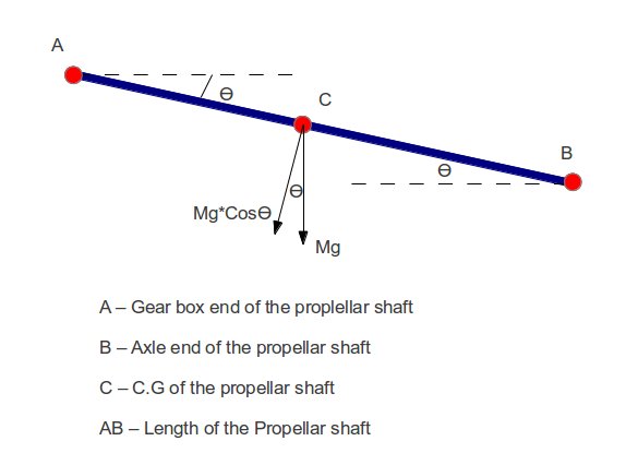
Propeller shaft in a geared controllable pitch. δ 5mgcos θ L3384EJ 0. Computer Aided Design of propeller shaft in Solidworks software.
SkyCiv offers a wide range of Cloud Structural Analysis and Design Software for engineers. D 3 2013164. Figure 1 is taken from Gilmer and Johnson Introduction to Naval Architecture.
Due to the nature of these calculators Victoria Propeller Ltd. But as in propeller shaft only torsional shear stresses are acts significantly so we have to design shaft by using eqn 3 only. Lets calculate the advance ratio at an engine speed of 4300 RPM and a propeller diameter of 170 m approximately 57 inches with the aircraft flying at 120 knots.
The torque is often relatively constant at steady state operation. Power storage fraction 15 Shaft transmission efficiency. Most shafts will transmit torque through a portion of the shaft.
128661 mm2 Position of centroid - X. Static deflection is calculated from the equation. 38205 mm Position of centroid -.
Hub The hub of a propeller is the solid center disk that mates with the propeller shaft and to which the blades are attached. Regularly the shaft has a tubular section and is made in maybe a couple. 20 25 and 30.
162 Objective The objectives of this project are. The calculation goes as below. It is not good to have an axis of 7 m long.
13 Required prop pitch for top speed. Calculation of Twisting Moment Effect. Up to 24 cash back The Propeller Design Calculations Name.
To properly choose a propeller we must first understand some of the basic nomenclature used to describe propeller geometry. Design of Propeller Shaft dp Since the propeller shaft is subjected to both bending moment due to propeller weight and twisting moment diameter of propeller shaft dp 25 extra then the designed by pure torsion. 7614 mm Inner Diameter of section.
This free propeller shaft bearing spacing calculator helps you determine the maximum allowable unsupported length between two bearings on a propeller shaft based on shaft diameter max engine RPM gear ratio shaft weight and modulus of elasticity. To simplify this above calculation process we can find the least critical shaft diameter by using the following T e formula used for the shaft subjected to fluctuating and twisting and bending together. Aim of this project is to design analyze and simulate a propeller shaft which is optimized with respect to weight strength and reliability.
In here T is the twisting moment d is the diameter of. Hanqing Cai Student ID. Calculate maximum static deflection of the driveshaft δ.
You must put intermediate supports. The effect of the twisting moment is the shear stress which is the maximum at the surface of the shaft. Because of the rotation a twisting moment occurs on the shaft.
As a constantly evolving tech company were committed to innovating and challenging existing workflows to save engineers time in their work processes and designs. Propeller Shaft is the shaft that transmits power from the gearbox to the differential gear in a motor vehicle from the engine to the propeller in a boat or flying machine. 090 desired speed divided by max prop shaft rpm to give prop feet per minute.
The design of hollow shaft consists of determination of correct inner and outer diameters from strength and rigidity basis. The calculator utilizes the following industry accepted formula endorsed by shaft. 1710 Estimated prop slip at required top speed.
42 Design of propeller shaft. This equation is used to calculate the effect of the twisting moment. The shear stress due to the torsion.
Shaft calculations such as torsional vibration and shaft alignment needs caused by mass and gas forces of the engine and by the mass inertia of the propeller. Autmobile Propeller Shaft Design Calculation- Part1 June 13 2012 Simplified ASME Pressure Vessel Design Calculation Example Part 2- Vessel Sizing December 13 2011 Kinetic Energy Recovery System How it Works November 14 2014. Ships RU SHIP Pt4 Ch2 Sec2 and shaft design as presented in this class guideline.
The other classification societies use the same formula. 1581139 7854 d 3. A free body dia-gram of the shaft will allow the torque at any section to be determined.
6481 Area of section. I do not know. In this part of the automobile propeller shaft design calculation tutorial we will see the critical speed calculation procedure for the example problem.
I have extracted three pitch angles from the graph above. The propeller is keyless fitted on to the shaft taper by a shrinkage method in compliance with Ch 1 8ec 8 312 or the propeller boss is attached to an integral propeller shaft flange in compliance with 251 the sterntube of the propeller shaft is oi I I ubricated and provided with oil realing glands approved by the Society or when the. Design of propeller shaft Calculation for Moment of Inertia of propeller shaft.
Design of propeller shaft for reduction in weight. Fluid dynamic calculations CFD for propulsion effectiveness and cavitation of propellers propeller caps pumps and other fluidic components. The calculator utilizes the following industry accepted formula endorsed by.
Outer Diameter of section. Let i o D C D 4 Where D i inner dia. The diameter of the propeller is a much more complicated issue that I can not help you.
Typically the torque comes into the shaft at one gear and leaves the shaft at another gear. Section 1 Class guideline. The propeller shaft is geared down by a ratio of 227.
1085 Theoretical required prop pitch in inches.
2

Propeller Shaft Design Software Skf Solution Factory Marine Services Calculation For Ships

Propeller Shaft And Drive Shaft Automobile
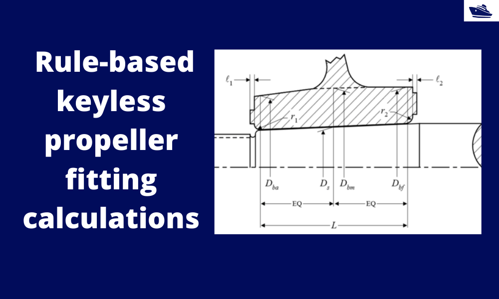
How To Do Rule Based Fitting Calculations Of A Keyless Propeller Thenavalarch
Dnv Gl The Shaft Calculation Software By Imt

Propeller Shaft And Drive Shaft Automobile
Pdf Design Optimization Of Automotive Propeller Shafts
Drive Shaft Design Calculation For Automobile
0 comments
Post a Comment